
Learn about gutter water collection by building a DIY rainwater collection system to water your garden and fill stock tanks.
Lisa and I own 21.5 forested acres in western Washington state. As retirees, we maintain a small hobby farm, grow vegetables in raised beds, and care for our 20,000-square-foot garden specifically designed for the benefit of native pollinators.
And although our 65-foot well taps into a shared aquifer with ample storage, collecting rainwater for non-potable use made sense for long-term sustainability. Rainwater-collection kits sold by vendors for the do-it-yourself homeowner were too small or impractical for our needs, so we decided to start from scratch with our own design. A year after our initial installation, and with a few adjustments along the way, our system works wonderfully. The only required maintenance is cleaning debris from the gutters and draining the underground pipes and pump in fall
DIY Rainwater Collection System Calculations
To build a rainwater-collection system like ours, you’ll need to consider two calculations. The first and most important is the size of the system, and the second is its capacity. We estimate our 300 square feet of raised garden beds require 2 inches of water twice a week from June 15 to September 15 (12 weeks). This estimate is based on our experience, so you may need to adjust for your own circumstances. Knowing there’s 0.62 gallons of water in 1 square foot, 1 inch high, our calculation (0.62 gallons x 300 square feet x 2 inches per week x 12 weeks) works out to 4,464 gallons. Therefore, we installed two 2,000-gallon tanks. The additional 464 gallons comes from collected winter overflow and is routed into stock tanks and an occasional summer shower.
Audio Article:
The second calculation is the number of inches of rain required to fill the system. Our 36-by-64-foot barn with a 6/12 pitch roof and 2-foot eaves (approximately 2,400 square feet) fills the 4,000-gallon reservoir and underground pipes with approximately 3 inches of rain. Because we’re on the west side of the Cascade Range, the tanks fill in no time, so our design includes a robust maintenance-free overflow bypass.
Component Considerations
Next, we gathered the parts to assemble the system. Luckily, the two tanks were available from a local vendor, so there was no delivery charge. The underground pipes, risers, fittings, and valves are all Schedule 40 PVC. We purchased the microfilter placed between our gutter and barn riser from a vendor specializing in rainwater collection. The importance of the microfilter cannot be overemphasized, especially with the amount of debris landing on our barn roof. Without this filter, the tank would require frequent cleaning.
Our design, based on hydrology 101, is simple. The top of each riser, one on each side of the barn, interfaces with its respective roof gutter through the microfilter. The bottom of each barn riser ties into an underground pipe buried 18 inches deep. From there, the underground piping system is constructed with wye, tee, and 90-degree fittings. We also needed pipe-diameter reducers. The entire piping system must be sealed to prevent leaking and, most important, to maintain the vacuum required to fill the tank from below. In theory, the top of the barn riser must be at least the same elevation as the top of the tank. However, in practice, we kept the top of this riser 12 inches higher in elevation for every 50 feet of distance to the tank, allowing for real world conditions.
Storage tanks. We used two tanks rather than one 4,000-gallon tank to keep the tank height to a minimum and avoid appearing like an industrial site. Unfortunately, this meant the second tank had to be set 17 inches below ground level to compensate for the grade between the two tanks, creating additional work and expense. To avoid wasting storage capacity, we kept the two tanks identical, their height at the same elevation, and the distance between them at a minimum.

The pipe layout underground doesn’t matter in terms of slope, assuming no portion rises to an elevation above the bottom of the lowest tank. This became an issue when setting the second tank below ground level.
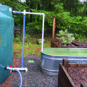
Unique to our system is the clear PVC riser between the top and bottom thresholds, located at the tank nearest the garden beds (our primary tank). This clear PVC acts as a site glass so we know when the tank is near empty, an aid to prevent pump damage. There’s a cross-section fitting at the top of the clear PVC riser with a removable plug, which allows for easy cleaning should algae buildup occur. Also, the top overflow pipes and fittings aren’t glued, for easy reconfiguration if necessary. A 2-to-11⁄2-inch reducer is required to transition from the lower and upper tank thresholds.
Valves. After sizing the system, the second most important step is the placement of valves. It’s slightly more involved with the second tank, but not complicated. In our situation, we installed five inline quarter-turn ball valves of various sizes. The primary tank has three valves. One isolates the pump, and when closed, the pump can be drained to prevent freeze damage in winter. The pump threshold is higher than the pump itself, so it can be primed by gravity come spring. The second valve disconnects the primary tank from the underground pipes. The third is located in the drain basin. This allows for the entire underground pipe system and clear PVC riser to drain should a hard freeze be in the forecast.

For the second tank, there are two valves. One valve isolates the tank from the underground pipes, and the other allows this tank to drain without necessarily affecting the primary tank or the underground pipes. The two valves interface with the lower threshold by using a 2-inch tee PVC fitting.
To better understand the use of valves, consider our system as three components: the two tanks and the underground pipes. Essentially, the valve configuration gives flexibility and minimizes water loss should isolating any one or two components from each other become necessary.
Downspout interface. We reconfigured the gutter to downspout interface with 1-1/2-inch PVC pipe that can rotate away from the microfilter. The redirected flow keeps unwanted debris and soap out of the system when we’re flushing the gutters of needles or cleaning solar panels located on the south-facing barn roof. Consider placing a 1-1/2-inch PVC pipe 1-1/4 inches high inside the gutter at the downspout to limit debris from accumulating on the microfilter. Of course, the downside of doing so means water will always be present in the gutter. A 3-to-2-inch reducer, placed underground, is required to transition from the barn riser to the primary tank’s lower threshold. Placing the reducer closest to the barn has minimized the stored water in the underground pipes.

Tank interiors. Inside the primary tank is a float with an inline filter connected to the pump threshold through a flexible suction hose long enough to reach the top of the tank. When the tank is nearly empty, the float and filter are slightly elevated from the bottom of the tank to minimize stirring up settled debris. Barbs are used as an interface between the suction hose, tank threshold, and pump. These internal tank parts are available from most vendors selling rainwater-collection systems.
Stock tanks. The stock tanks fill with overflow from the reservoirs’ top threshold. Excess water from these tanks simply runs over the side onto the ground away from the buildings, as any drainage would. These tanks supplement our storage capacity, and the water provided keeps fresh water flowing to our chickens and goats.
The pump. I recommend a 1.0-horsepower pump or lower to reduce damaging fragile plants in early spring; there’s plenty of pressure to reach our farthest raised bed. If your pump is kept outside, consider a cover to keep it protected and increase its life span.

When selecting a pump, consider the “demand” versus “delivery” option. The demand pump we purchased is energized by an internal switch, so when the pressure drops, water flows, and its pump is always ready. This benefits automated watering systems, because manual activation, as on a delivery pump, isn’t necessary. However, a drawback to the demand pump is the risk of draining the tank should a hose leak or be inadvertently left open.
We may install an automatic drip system someday, so we opted for the demand pump. For now, however, the pump’s exterior electrical outlet is wired through the light switch inside the greenhouse, so the pump is energized only when the greenhouse light is on. Seeing the light on after I’m done watering, especially at night, acts as a reminder to turn off the pump. It’s easy enough to reconfigure the wiring should we install a drip system.
Rules and Regulations
Before you embark on collecting rainwater with your own DIY system, check with county and state regulatory agencies to ensure water collection is allowed in your area. Rules and regulations vary, so it’s important information to have before you begin.
Jim Mahar is a retired electrical engineer and Master Gardener living in Washington state. Jim and Lisa practice conservation and, when not traveling, enjoy maintaining their extensive pollinator garden without the use of any pesticides. Their home is 100 percent energized with solar power and Jim frequently participates in community projects aimed to benefit our natural world.


